
Punching shear verification is a program that checks the Failure Limit State of concrete for punching shear in flat and waffle slabs exposed to concentrated loads from rectangular or circular supports.
The program can check slabs with or without transverse punching shear reinforcement, takes into account the presence of openings or lightweight zones in the slab, and the position of the supports (internal, edge or corner).
CYPECAD also carries out this punching shear check. 
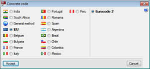
The concrete codes implemented in Punching shear verification are the following:
- ABNT NBR 6118:2007 (Brazil)
Norma Brasileira ABNT NBR 6118 (2007). Projeto de estruturas de concreto - Procedimento.
- ABNT NBR 6118:2014 (Brazil)
Norma Brasileira ABNT NBR 6118 (2014). Projeto de estruturas de concreto - Procedimento.
- ACI 318M08 (USA)
Building Code Requirements for Structural Concrete.
- ACI 318M11 (USA)
Building Code Requirements for Structural Concrete (ACI 318M-11)
- BAEL-91 (R-99) (France)
Fascicule nº62 - Titre I - Section I Règles techniques de conception et de calcul des ouvrages et des constructions en béton armé suivant la méthode des états limites - BAEL 91 révisé 99.
- CIRSOC 201-2005 (Argentina)
Reglamento Argentino de Estructuras de Hormigón CIRSOC 201 (Julio 2005).
- IS 456: 2000 (India)
Indian Standard. Plain and reinforced concrete code of practice (Fourth Revision).
- Eurocode 2
Las adaptaciones para cada país incluyen su correspondiente documento nacional de aplicación.
- Eurocode 2 (EU)
EN 1992-1-1:2004/AC 2008.
Design of concrete structures. Part 1-1: General rules and rules for buildings. - Eurocode 2 (Belgium)
NBN EN 1992-1-1 ANB.
Calcul des structures en béton. Partie 1-1 : Règles générales et règles pour les bâtiments. - Eurocode 2 (Bulgaria)
Design of concrete structures. Part 1-1: General rules and rules for buildings.
- Eurocode 2 (France)
NF EN 1992-1-1 :2005/NA: Mars 2007.
Calcul des structures en béton. Partie 1-1 : Règles générales et règles pour les bâtiments. - Eurocode 2 (Portugal)
NP EN 1992-1-1:2010/NA.
Projecto de estructuras de betão. Parte 1-1: Regras gerais e regras para edifícios. - Eurocode 2 (Romania)
Design of concrete structures. Part 1-1: General rules and rules for buildings.
- Eurocode 2 (EU)
- EHE-08 (Spain)
Instrucción de Hormigón Estructural.
- Nch430.Of2008 (Chile)
Norma Chilena oficial NCh430.Of2008.
- NTC: 14-01-2008 (Italy)
Norme tecniche per le costruzioni.
- NTC: 14-01-2008 (Italy)
- NTCRC:2004 (Mexico)
Normas técnicas complementarias del reglamento de construcciones para el Distrito Federal.
- NTE E.060: 2009 (Peru)
Reglamento Nacional de Edificaciones. Norma E.060 Concreto Armado (2009).
- NSR10 (Colombia)
Reglamento Colombiano de Construcción Sismo Resistente NSR-10. Título C - Concreto estructural.
- NSR10 (Colombia)
- SABS 0100 (South Africa)
SOUTH AFRICAN STANDARD Code of practice The structural use of concrete Part 1: Design
More concrete codes will be implemented in upcoming versions.
Punching shear verification in CYPECAD
CYPECAD checks the Failure Limit State of concrete for punching shear using two methods: Point tangential stress check and Check in accordance with the design standards. The latter method is that used by the 'Punching shear verification' program.
More information on the punching shear checks carried out by CYPECAD.
Punching shear verification is located in the Structural elements group of the main CYPE program menu. Once selected, the data introduction process for a new job (File > New) is carried out in two phases:
- Definition of the general data of the job (codes, materials, combinations and loadcases)
- Data introduction of the supports and floor slabs (geometry, forces and punching shear reinforcement)
Definition of the general data of the job (codes, materials, combinations and loadcases)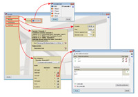
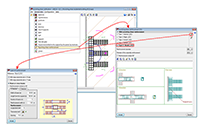
The general data of a new job is introduced with help from an assistant which is executed automatically once a new job is created (File > New), and the name and description of the job have been provided.
The assistant asks for the following data:
- Codes
- Materials
- Type of concrete
- Type of steel
- Maximum aggregate size
- Geometric cover
- Combinations
Snow level - Loadcase
- Definition of the Use category of the buildin
- Definition of the loadcase and combinations with other loadcases of the same nature.
Once the data introduction using the assistant has concluded, the same data can be edited using the options within the General data menu (Materials, Combinations and Loadcases) or using the corresponding icons from the toolbar: ![]() (Materials),
(Materials), ![]() (Combinations) and
(Combinations) and ![]() (Loadcases).
(Loadcases).
Data introduction of the supports and floor slabs (geometry, forces and punching shear reinforcement)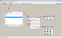
To introduce a support, users must select List of supports from the General data menu or press the ![]() button from the toolbar. The List of supports dialogue box will appear where users can create, duplicate or delete supports, as well as select the created support which is to be viewed on screen. When a support is created, users define its section type, its dimensions and the location of the supports which are to be introduced in the job.
button from the toolbar. The List of supports dialogue box will appear where users can create, duplicate or delete supports, as well as select the created support which is to be viewed on screen. When a support is created, users define its section type, its dimensions and the location of the supports which are to be introduced in the job.
Users will only view the selected column on-screen. Using the ![]() button of the toolbar, users can view the other supports that have already been defined.
button of the toolbar, users can view the other supports that have already been defined.
To edit the data of a support which has already been introduced, use the Support option from the General data menu or the ![]() button from the toolbar.
button from the toolbar.
More options are present in the General data menu and toolbar to define the following data: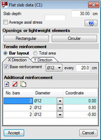
 Flat slab data
 - Depth
- Average axial stress
- Presence of openings or lightweight elements, rectangular or circular
- Tensile reinforcement definition, in the X-direction and Y-direction, with two possible ways to define it
- Bar layout
The spacing and diameter of the base reinforcement and additional reinforcement are provided for each direction (indicating the separation of the additional reinforcement with respect to the centre of the column taken as the origin). Regarding the additional tensile reinforcement, the bars have to be introduced, be well anchored and not be interrupted by any openings.
It is obligatory that the base or additional reinforcement be defined in both directions. Definition of both reinforcements is optional. - Total area
The total area of the reinforcement in tension is introduced directly and for each reinforcement direction. 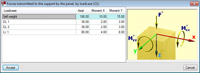
 Forces transmitted to the support by the panel, by loadcase
The forces transmitted by the floor slab to the support must be provided by loadcase, and with the corresponding axes sign criteria. This way, the introduction of the forces is faster and easier than having to indicate the forces along the edge of the critical perimeter of the slab. The program automatically carries out the force combinations in accordance with the selected code.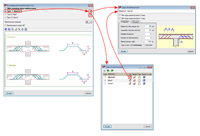
 Punching shear reinforcement
If reinforcement is provided, the type of reinforcement that can be introduced in the current version consists of:
- Bars with a 45° slope
Can be anchored at the support or be continuous. More types of reinforcement will be provided in upcoming versions.
- Beam or Crossed beams
Several beams can be included in one or both directions (appropriate for punching shear reinforcement in the case of very wide columns).
- Bars with a 45° slope
In both cases, users must indicate the reinforcement provided in a specific width, which depends on the selected code.
Once the data has been introduced, the viewed support can be checked on-screen using the Check option in the General data menu or the ![]() button from the toolbar.
button from the toolbar.
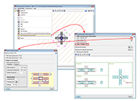
The program carries out the punching shear check using the following steps:
- Critical punching shear area
Obtains and marks on-screen, the worst case critical punching shear area around the support, defined by its critical perimeter.
- Worst case forces
Obtains the worst case forces transmitted by the floor slab to the support along the punching shear surfaces.
- Stress calculation
Calculates the stresses along the critical perimeter and compares them to the stress resistance of the concrete.
- Check of the provided punching shear reinforcement
If users introduce additional punching shear reinforcement, the program verifies the behaviour of the reinforcement distribution in accordance with the selected code.
Using the Check option in the General data menu or the ![]() button from the toolbar, the following results can viewed on-screen or in a report:
button from the toolbar, the following results can viewed on-screen or in a report:
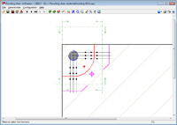
- Verification critical perimeter (red)
- Perimeter adjacent to the support (blue)
- External perimeter of the reinforcement (magenta) if punching shear reinforcement is provided.
Displayed with these perimeters is their centre of gravity with its corresponding colour.
The reports display all the checks carried out on the geometric and resistance specifications, and that the reinforcement distribution is in accordance with the selected code.
When the Check option in the General data menu or the ![]() button from the toolbar is selected, the program asks "Would you like to view the complete report of the assessed checks?". If the answer is yes, the report will be displayed on-screen and can be printed or exported to various formats. Only the report of the support currently viewed on-screen will be exported or printed.
button from the toolbar is selected, the program asks "Would you like to view the complete report of the assessed checks?". If the answer is yes, the report will be displayed on-screen and can be printed or exported to various formats. Only the report of the support currently viewed on-screen will be exported or printed.
To obtain the verification reports of all the supports of the job in a single document, the Job report option must be selected (File > Print).
Using the Job drawing option (File > Print), users can configure and generate drawings of all the supports of the job. These drawings display the details of the selected reinforcement and its take-off.
Tel. USA (+1) 202 569 8902 // UK (+44) 20 3608 1448 // Spain (+34) 965 922 550 - Fax (+34) 965 124 950